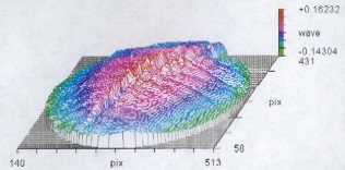
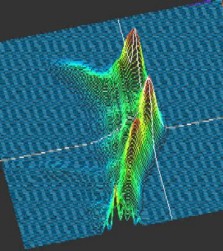
Fig.1. Wavefront aberrations in the final disc amplifier of 40-mm diameter, 17-mm thickness, and α=2.3 at 532 nm
Joint work with H. Baumhacker, G. Pretzler, K. J. Witte, M. Hegelich, M. Kaluza, and S. Karsch
Max-Planck-Institut für Quantenoptik, Hans-Kopfermann-Straße 1, D-85748 Garching
We describe a novel scheme consisting of two deformable mirrors that can free ultrashort laser pulses from simultaneously present severe wavefront distortions and strong intensity-profile modulations. This scheme is applied to the MPQ 10-TW TiS laser facility ATLAS. We demonstrate that thereby the focusability of the ATLAS pulses can be improved from 1018 to 2x10¹⁹W/cm²
Due to the large bandwidth, favorable saturation energy density, and good thermal conductivity of titanium:sapphire (TiS), multi-stage CPA lasers using this material as the amplifying medium are well suited to deliver fs-pulses in the multi-10 Terawatt range at the 10-Hz level1,2,3. Focusing these pulses to >1018 W/cm² for light-matter experiments in the relativistic regime (see, f. e., ref. 4) requires a beam quality as close as possible to the diffraction limit. However, growth defects and refractive index changes resulting from pump-induced temperature gradients in the large-sized crystals in the final amplifiers can cause considerable wavefront distortions. Cooling the crystal to liquid-nitrogen temperature can reduce aberrations due to pump-induced temperature gradients.2,5 This results from the thermal behavior of TiS. Its thermal conductivity at –170 °C is about 30 times larger than that at room temperature and its refractive index change with temperature, dn/dT, decreases by a factor of 7. Hence, strong temperature and refractive index gradients cannot build up.
Besides cooling,another possibility to correct the wavefront distortions is to use adaptive optics. This can be achieved with a single deformable mirror as long as the crystals perturb the wavefront only without modulating the intensity or fluence profile.6,7
However, the situation is more complex in presence of strong intensity modulations. They occur when the amplifying crystal exhibits growth defects which do not disappear upon cooling and get even worse when the crystal is loaded. In the final disc amplifier of the ATLAS (Advanced Titanium:Sapphire LASer) facility at MPQ, such a defect exists (see Fig.1). In order to clean a pulse from simultaneously present intensity profile modulations and wavefront aberrations, two deformable mirrors are needed. The first smoothens the intensity profile in a plane chosen downstream from the mirror. The second mirror located in this plane or close to it corrects the wavefront. In the following, we show how this novel concept is successfully implemented in the ATLAS beam line.
In Fig.2, the beam path in the final ATLAS amplifier is shown schematically. The crystal of 40-mm outer diameter is pumped from two sides by 2-J pulses from a frequency-doubled Nd:YAG laser. The TiS pulse provided by the front end has a center wavelength of 790nm, a bandwidth of 8 nm, and is stretched from 100fs to 200ps.8 It passes the crystal four times to be amplified from 200 mJ to 1.5J and then runs through the spatial filter (SF2) in which its diameter increases from 18 to 63mm. In the evacuated compressor chamber equipped with two parallel holographic gold gratings, it is recompressed to 130fs. The pulse serves three different target chambers which are connected to the compressor chamber by evacuated tubes.
The first deformable mirror DM1 with an effective aperture of 30mm and 17 electrodes arranged in two rings is placed in the beam line before the pulse makes the final transit through the amplifier. The second deformable mirror DM2 with an effective aperture of 80 mm and 33 electrodes arranged in three rings is incorporated into the beam line shortly after the compressor.9 Both mirrors carry a high-reflective dielectric coating with a damage threshold of 1 J/cm².
When a plane mirror is used instead of DM1, the fluence profile in the compressor is double-peaked (see Fig.3a) with a maximal energy density of 300mJ/cm² at a pulse energy of 1.3J at the compressor entrance clearly proving the poor quality of the amplifying crystal. The pulse is largely freed from its highest spatial frequency components picked up in the crystal when passing the pinhole of SF2 whereby it suffers a slight energy loss. However, the peak fluence of 300mJ/cm² is beyond the grating damage threshold of 150mJ/cm². The double-peaked fluence pattern would hence limit the compressor throughput to only about 500mJ. When the plane mirror is replaced by DM1, the fluence profile in the compressor can be effectively smoothened (see Fig.3b). It turned out that the best electrode voltage settings can be manually found by trial and error rather quickly. This reduces the peak fluence to 90mJ/cm² so that the pulse can be safely transmitted through the compressor up to a maximal output energy of 1.2J. The homogenized fluence profile remains stable over weeks at constant voltage settings of DM1. Inside the compressor and up to a few meters downstream, the smoothened profile remains rather similar.
As already stated, the action of DM1 does not generate a plane wavefront in the compressor; the aberrations due to the amplifying crystal get, however, modified. Their cancellation is the task of DM2 which for safety reasons is best placed behind the compressor because then highly peaked intensity patterns which might occur during the optimization procedure of DM2 cannot damage the gratings. The compressor is hence fed with a chirped pulse having a distorted wavefront. In the following, we investigate the effects arising therefrom on the space-time characteristics of the recompressed pulse both analytically and by ray tracing. We show that the aberrations can be tolerated if certain conditions are met.
For the theoretical treatment, we replace the real pulse by a converging model pulse with a spherical wavefront of a curvature equivalent to the maximal local curvature occurring in the real distorted wavefront. Note that the passage of a convergent or divergent beam through a standard two-grating compressor run in double pass is a problem of general interest which has not been looked at so far.
First we investigate the recompression of the convergent pulse. For this purpose, it is sufficient
to consider a single ray having an angle α+Δα
with the grating normal in the dispersion plane where α
is the incidence angle of the central ray which the compressor is adjusted for: each ray entering the compressor under this angle in the dispersion plane
leaves it by exactly running backwards the incoming path. We find that the relative uncompensable changes of the higher-order dispersion coefficients
experienced by the tilted ray scale as  with i=2,3,4. There is no term linear in
Δα because the corresponding contributions resulting from the first and second
pass through the compressor cancel each other. This is a definite advantage
of a double-pass compressor over a single-pass compressor. Since at ATLAS
Δα is at most a few mrad, the pulse recompression is practically equal to that of a
parallel beam. This also holds true for the non-dispersion plane (perpendicular
to the dispersion plane). These deviations are too small to be experimentally
verified since they are within the shot-to-shot fluctuations of the
pulse-duration measurements of 130±15fs.
with i=2,3,4. There is no term linear in
Δα because the corresponding contributions resulting from the first and second
pass through the compressor cancel each other. This is a definite advantage
of a double-pass compressor over a single-pass compressor. Since at ATLAS
Δα is at most a few mrad, the pulse recompression is practically equal to that of a
parallel beam. This also holds true for the non-dispersion plane (perpendicular
to the dispersion plane). These deviations are too small to be experimentally
verified since they are within the shot-to-shot fluctuations of the
pulse-duration measurements of 130±15fs.
Secondly, the originally spherically convergent beam turns astigmatic when leaving the compressor
leading to the occurrence of two focal lines instead of a single point focus.
This happens because the beam geometry is differently modified in the
dispersion and non-dispersion planes of the compressor. The line-foci
separation is independent on color and given by  where D is the oblique grating distance at
 is the diffraction angle, N
is the groove density of the grating,and λ0 is
the pulse center wavelength. The ratio of the line-foci separation to the
average radius of curvature of the wavefront is a measure of the strength of
the astigmatism. For a parallel beam, astigmatism is absent because the radius
is infinite. For ATLAS, we have D=67cm, N=1800grooves/mm,
λ0=790nm, α=50°, β0=37°
leading to a line-foci separation of 65cm. From wavefront measurements taken
at the compressor exit, we know that the local radius of curvature is always
≥15m. If a value of 15m is assigned to the model
pulse, the compressor-induced astigmatism turns out to be weak. It is
easily correctable by a deformable mirror since the necessary surface displacement
is ≤1μm. The compensation of the original beam convergence is not a problem either.
is the diffraction angle, N
is the groove density of the grating,and λ0 is
the pulse center wavelength. The ratio of the line-foci separation to the
average radius of curvature of the wavefront is a measure of the strength of
the astigmatism. For a parallel beam, astigmatism is absent because the radius
is infinite. For ATLAS, we have D=67cm, N=1800grooves/mm,
λ0=790nm, α=50°, β0=37°
leading to a line-foci separation of 65cm. From wavefront measurements taken
at the compressor exit, we know that the local radius of curvature is always
≥15m. If a value of 15m is assigned to the model
pulse, the compressor-induced astigmatism turns out to be weak. It is
easily correctable by a deformable mirror since the necessary surface displacement
is ≤1μm. The compensation of the original beam convergence is not a problem either.
Thirdly, chromatic aberration is also present behind the compressor because the path lengths of
the individual spectral components through the compressor are different. Even
though for each color the line-foci separation is the same as stated above thus
allowing the cancellation of the astigmatism, the line-foci pairs of the
individual colors do not fall upon each other but spread along the beam axis.
Relative to the position of one of the two focal lines belonging to the spectral
component at λ0, the position of the corresponding focal line due to
the wavelength λ0+δλ is displased by
 . This phenomenon cannot be compensated by DM2. The
beam emerging from DM2 will be parallel for the spectral components around λ0
, but divergent for the components with λ<λ0
and convergent for those with λ<λ0.
When this beam is focused by the off-axis parabola,
the focus is no longer point-like, but spreads out along the beam axis in form
of a line since each spectral component has its own focus located at a different
position. A criterion as to the tolerability of this spreading is to require
that the foci of all contributing colors for which we take those contained
within four times the spectral FWHM, Δλ, lie within the Rayleigh length of the spectral beam component at
λ0. This happens when the local radius of curvature,
R, of the aberrated wavefront upon entering the compressor meets the condition
. This phenomenon cannot be compensated by DM2. The
beam emerging from DM2 will be parallel for the spectral components around λ0
, but divergent for the components with λ<λ0
and convergent for those with λ<λ0.
When this beam is focused by the off-axis parabola,
the focus is no longer point-like, but spreads out along the beam axis in form
of a line since each spectral component has its own focus located at a different
position. A criterion as to the tolerability of this spreading is to require
that the foci of all contributing colors for which we take those contained
within four times the spectral FWHM, Δλ, lie within the Rayleigh length of the spectral beam component at
λ0. This happens when the local radius of curvature,
R, of the aberrated wavefront upon entering the compressor meets the condition
 . The scaling of R with
Δλ is worth noting; very short pulses
with a bandwidth of 50nm or more need to be extremely well collimated in order
to avoid intensity degradation in the focus. For ATLAS with Δλ=8nm,
we have to meet R>15m which is indeed the case as mentioned above.
. The scaling of R with
Δλ is worth noting; very short pulses
with a bandwidth of 50nm or more need to be extremely well collimated in order
to avoid intensity degradation in the focus. For ATLAS with Δλ=8nm,
we have to meet R>15m which is indeed the case as mentioned above.
We generate a parallel beam with DM2 by comparing the actual wavefront measured with a Shack-Hartmann sensor (see Fig.2) to a reference wavefront obtained from a diode laser running at 790nm. Its output is expanded to provide a beam of 63-mm diameter with a plane wavefront. This beam is once analyzed with the Shack-Hartmann sensor; the result is stored in the computer for subsequent use. The voltage settings to be assigned to the electrodes of DM2 have then to be found such that the wavefront of the ATLAS pulse matches the reference wavefront as closely as possible. Because of the high thermo-mechanical stability of the ATLAS facility, this can in principle be manually achieved by trial and error. It turned out, however, that it is not as easy as in case of DM1 but takes hours. We therefore realized the closed-loop solution. The algorithm which calculates the DM2 voltage settings needs the response functions of the 33 electrodes of DM2 as input. These are in-situ generated once only and then stored as an average over 10 laser shots; this takes about one minute. The deviations between the actual and reference wavefronts are minimized by repeatedly applying the least mean square fit. Usually, several ten iterations are needed which currently takes a few seconds. With this closed-loop operation, the peak-to-valley wavefront deformation could be reduced from originally 10λ to less than λ/4. The voltage settings corresponding to minimal wavefront distortion are stored. They can be used for hours, because the shot-to-shot fluctuations of the wavefront remain small. For routine operation of ATLAS, the beamsplitter feeding the Shack-Hartmann sensor has to be removed from the beamline in order to keep the B-integral low. In case of a deteriration, f.e. due to a thermal drift, the whole procedure beginning with the recording of the response functions has to be repeated.
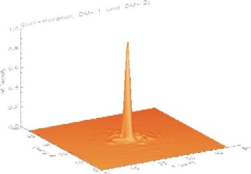
We checked the quality of the corrected wavefront in each target chamber by measuring the fluence pattern in the focus of the F/3 off-axis parabola. In each case, we obtained the same result for thousands of shots. With DM1 turned on and DM2 operated to provide a plane surface, we find the multiple-peaked fluence pattern depicted in Fig.4a. The Strehl ratio amounts to 0.1 only. When DM2 is, however, locked to operation for minimal wavefront distortion, we find a dramatic improvement as proven by Fig.4b: A single peak appears, 65% of the pulse energy is contained within the diffraction limited diameter (DLD), the Strehl ratio climbs up to 0.8, and the mean intensity inside the DLD is raised by more than a factor of ten from ~1018 to 2x10¹⁹W/cm². The halo is attributed to high-order spatial frequencies still passing the pinhole of SF2 and not correctable by DM2.
That the beam quality has indeed been remarkably improved is also corroborated by recently performed neutron experiments in which solid deuterium targets were irradiated with ATLAS pulses. We observed an increase in the neutron yield by almost two orders of magnitude when wavefront-corrected pulses were used.
In summary, we have shown that a combination of two deformable mirrors can free ultrashort laser pulses from simultaneously present severe wavefront distortions and strong intensity-profile modulations without any penalty in recompression fidelity.
This work was supported by the Commission of the EU within the framework of the Association Euratom-MPI für Plasmaphysik and the EU project ADAPTOOL, Contract No. HPRI-CT-1999-50012
K. Witte’s e-mail address: klaus.witte[@]mpq.mpg.de
1. K.Yamakawa, M. Aoyama, S. Matsuoka, T. Kase, Y. Akahane, and H. Takuma, Opt. Lett. 23, p.1468, 1998.
2. M.Pittman, J. P. Rousseau, L. Notebaert, S. Ferré, J. P. Chambaret, and G. Cheriaux, CLEO 6-11 May 2001, Baltimore/MD, Advanced Program p.83.
3. M.P. Kalachnikov, I. Begishev, V. B. Karpov, P. V. Nickles, H. Schönnagel, and W. Sandner, CLEO 6-11 May 2001, Baltimore/MD, Advanced Program p.82.
4. C.Gahn, G. Tsakiris, A. Puhov, J. Meyer-ter-Vehn, G. Pretzler, P. Thirolf, D. Habs, and K. Witte, Phys. Rev. Lett. 83, p.4772, 1999.
5. G.Erbert, I. Bass, R. Hackel, S. Jenkins, K. Kanz, and J. Paisner, CLEO 91, OSA Technical Digest Series, pp.390-391, 1991.
6. K.Akaoka, S. Harayama, K. Tei, Y. Maruyama, and T. Arisawa, SPIE 3265, p.219, 1997.
7. F.Druon, G. Chériaux, J. Faure, J. Nees, M. Nantel, A. Maksimchuk, G. Mourou, J. Chanteloup, and G. Vdovin, Opt. Lett. 23, p.1043, 1998.
8. K.Yamakawa, P. Chiu, A. Magana, and J. Kmetec, IEEE J. Quant. Electron. QE-30, p.2698, 1994.
9. DM1 and DM2 were produced in the mainframe of a MPQ-IPLIT collaboration. For a previous mirror version see: J. Dainty, A. Koryabin, and A. Kudryashov, Appl. Optics 37, p.4663, 1998.